How Butt Splice Terminals Ensure Reliable Wire Connections (Complete Guide)
Jun 24, 2026
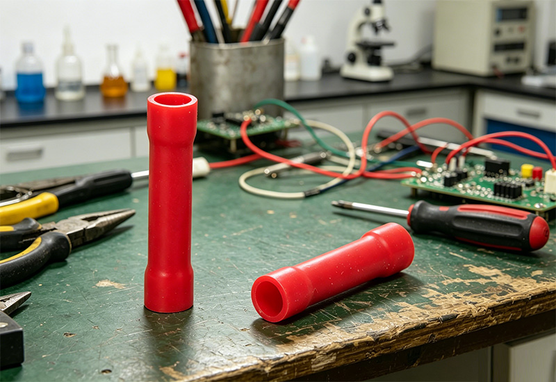
If you’re working in electrical sourcing or industrial procurement, you already know that a weak wire joint can bring an entire system down. A butt splice terminal is designed to solve exactly that problem—creating a stable, low-resistance, and mechanically secure wire-to-wire connection. In this guide, you’ll understand how Butt Splice Connector, Crimp Butt Connector, and industrial-grade solutions from Westlec ensure long-term wiring reliability in real-world applications.
How Butt Splice Terminals Ensure Reliable Wire Connections
When you evaluate wiring components as a buyer, reliability is rarely about one single feature—it’s a combination of geometry, material behavior, and installation consistency. A Butt Splice Terminal is engineered so that every step of the connection process reduces failure risk, even in demanding environments like automotive systems or industrial control panels.
Wire-To-Wire Connection Alignment Mechanism
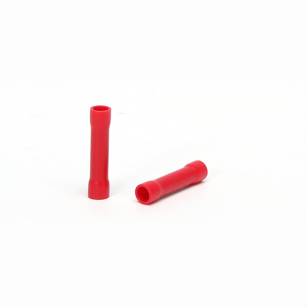
The first factor that defines reliability is how accurately two conductors align inside the terminal barrel. A Butt Splice Connector is designed with a symmetrical cylindrical structure that guides both wire ends into a perfectly centered position.
Once inserted, the internal barrel creates a controlled compression zone that ensures both conductors meet with uniform contact pressure. This eliminates uneven resistance points, which is something you often see in twisted or poorly soldered joints.
In practice, this is why technicians prefer crimp-based splicing in field maintenance—you get repeatability, not guesswork.
● Perfect axial alignment of conductors
● Stable insertion depth for both wire ends
● Even pressure distribution across contact area
● Reduced risk of partial conductivity failure
● Consistent performance across repeated installations
Mechanical Strength & Vibration Resistance
In industrial environments, electrical failure is often mechanical before it is electrical. Vibration, tension, and cable movement gradually degrade poor joints. A properly installed Crimp Butt Connector solves this by creating a cold-weld-like structure between wire strands and the metal barrel.
Once crimped, the connector behaves almost like a single solid conductor. That’s a big reason it’s widely used in automotive harnesses and machinery systems where movement is constant.
It’s not perfect in theory—but in real-world field conditions, it performs surprisingly well.
● High pull-out resistance after crimping
● Stable performance under continuous vibration
● Strain relief effect on conductor joints
● Reduced micro-movement at contact interface
● Long lifecycle in dynamic wiring systems
Material Selection For Electrical Stability
Now, here’s where many low-cost alternatives fail: material quality. A professional Electrical Terminal Manufacturer like Westlec typically uses tin-plated copper or high-conductivity copper alloys, which directly influence current stability and heat behavior.
Material selection determines whether the joint stays stable after thousands of thermal cycles—or starts degrading slowly over time.
Copper provides conductivity, tin plating reduces oxidation, and together they create a balance between performance and durability. It’s not flashy engineering, but it’s what keeps systems running.
● Tin-plated copper improves corrosion resistance
● High conductivity reduces voltage drop
● Stable thermal expansion behavior under load
● Longer operational lifespan in humid environments
● Reduced maintenance frequency in field applications
Types Of Butt Splice Terminals
Different environments require different insulation strategies. You don’t really choose based on “preference”—you choose based on exposure conditions, voltage levels, and maintenance expectations.
Vinyl Insulated Butt Splice Terminals
Vinyl types are the entry-level solution, typically used in controlled environments. They’re cost-effective and easy to install, which makes them common in general wiring systems where environmental stress is minimal.
They’re simple—but sometimes simple is exactly what procurement needs.
Nylon Insulated Butt Splice Terminals
Nylon insulation improves mechanical toughness and heat resistance. In industrial panels or automotive systems, this becomes the more balanced option between cost and durability.
It feels like the “default professional choice” in many projects.
Heat Shrink Butt Splice Terminals
This is where sealing becomes critical. Heat shrink versions provide adhesive-lined insulation that protects against moisture, dust, and corrosion.
You’ll often see these used in marine or outdoor installations where failure is expensive—not just inconvenient.
Color Coding System For Wire Gauge Matching
Wire mismatch is one of the most common sourcing mistakes. Color coding exists to reduce that risk.
Color
Wire Range (AWG)
Typical Use
Red
22–16 AWG
Low current circuits
Blue
16–14 AWG
General industrial wiring
Yellow
12–10 AWG
Higher load applications
It looks basic, but it prevents costly installation errors in bulk projects.
Step-By-Step Guide: How To Crimp Butt Splice Terminals
When you’re evaluating installation reliability, the process matters as much as the product.
● Strip wire insulation to correct length
● Match terminal size with wire gauge
● Insert wire ends fully into barrel
● Apply calibrated crimping tool
● Perform pull-test for mechanical validation
● Inspect insulation coverage and seal integrity
A small mistake in crimp force can change everything—and that’s usually where cheap connectors fail.
Applications Of Butt Splice Terminals
You’ll see Butt Splice Terminal solutions across multiple industries, especially where reliability matters more than cost per unit.
● Automotive wiring harness systems
● Industrial automation control panels
● Renewable energy installations
● Marine electrical systems
● HVAC and building wiring systems
In many procurement cases, the decision isn’t “if” you use them—it’s which grade you choose.
Common Mistakes To Avoid
Even good components fail when misused, and this is something buyers often underestimate.
● Using incorrect wire gauge size
● Under-crimping or over-crimping
● Mixing stranded and solid wires improperly
● Ignoring environmental sealing requirements
● Skipping pull-test verification
These are small details, but they decide long-term system reliability.
Why Choose High-Quality Butt Splice Terminals From Westlec
When you compare suppliers, the difference usually isn’t visible at first glance. It shows up after installation—sometimes months later.
Westlec focuses on consistent crimp performance, stable material quality, and scalable manufacturing control as an Electrical Terminal Manufacturer supporting industrial procurement needs.
● Stable conductivity under load conditions
● Reliable crimp geometry consistency
● Industrial-grade corrosion resistance
● OEM/ODM production capability
● Designed for long-term electrical stability
FAQ
Are Crimp Connectors Reliable?
Yes—when properly crimped, they create a gas-tight joint with stable conductivity and strong mechanical bonding.
How Butt Splice Terminals Work?
They connect two wire ends inside a metal barrel using compression crimping to form an electrical and mechanical bond.
What Is A Butt Splice Terminal?
It is a wire connector used to join two conductors end-to-end in a straight-line configuration.
Can I Reuse A Butt Splice Connector?
No, most crimp-based terminals are designed for single-use applications.
Are Butt Splice Connectors Waterproof?
Heat shrink versions can provide waterproof and moisture-resistant sealing.
What Industries Use Butt Splice Terminals Most?
Automotive, industrial automation, renewable energy, and marine systems.
What Is The Difference Between Crimp And Solder Connection?
Crimping uses mechanical compression; soldering uses melted alloy. Crimping is more vibration-resistant in most field applications.
What Is Difference Between Insulated And Non-Insulated Butt Splices?
Insulated versions provide safety and environmental protection; non-insulated require external insulation.
What Quality Standards Should Electrical Terminal Manufacturer Follow?
Typically UL, CE, RoHS, and ISO quality management systems are expected in industrial procurement.
Conclusion
In real-world electrical systems, reliability is never accidental—it’s engineered. A Butt Splice Terminal provides a controlled, repeatable method for joining conductors, combining mechanical strength, electrical stability, and environmental protection in a single solution. Whether you are sourcing for automotive production, industrial control systems, or energy infrastructure, the difference between average and high-quality components becomes visible over time, not on day one.
For procurement teams, choosing a trusted Butt Splice Connector supplier is less about price and more about lifecycle performance. Westlec positions itself exactly in that space, delivering consistent crimp quality and stable material performance for demanding applications.
If you are evaluating sourcing options, it may be worth looking beyond specifications—and focusing on how the connection performs after installation, vibration, and time.
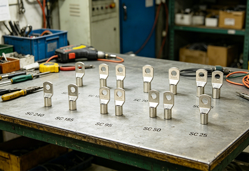
The performance of a Copper Lug Connector begins long before installation. Manufacturing quality determines conductivity, mechanical strength, corrosion resistance, and service life.
Professional manufacturers follow a series of controlled production processes to ensure every terminal meets industry requirements.
Copper Tube Selection
Everything starts with raw materials.
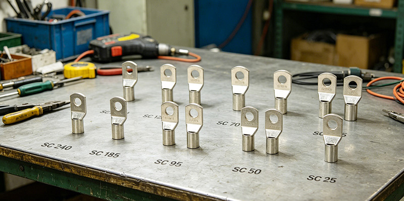
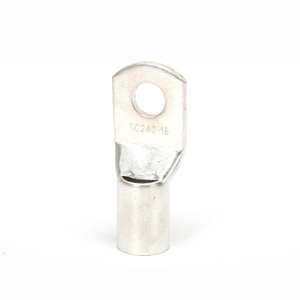
High-quality Copper Tube Terminal Lugs are typically manufactured from seamless electrolytic copper tubes with a purity level exceeding 99.9%. Pure copper offers excellent electrical conductivity while maintaining the mechanical strength needed for heavy-duty applications.
A reputable manufacturer will carefully inspect incoming copper materials to verify:
● Copper purity
● Wall thickness consistency
● Surface quality
● Dimensional accuracy
● Conductivity standards
Low-grade copper may appear similar externally, but often results in increased electrical resistance and reduced lifespan.
Cutting And Forming
After material verification, copper tubes are cut into precise lengths according to product specifications.
Advanced CNC cutting equipment helps ensure:
● Uniform barrel length
● Smooth cutting edges
● Consistent dimensions
● Minimal material waste
The terminal palm is then formed through stamping and pressing operations.
This stage determines the final shape of the terminal and directly affects installation compatibility.
Punching And Hole Making
The mounting hole is one of the most critical features of a terminal.
Precision punching machines create stud holes designed for common bolt sizes such as:
● M6
● M8
● M10
● M12
● M16
Accurate hole dimensions ensure secure fastening while preventing unnecessary movement during operation.
Many industrial users prefer Ring Type Cable Lug designs because the closed-ring structure provides superior vibration resistance compared to fork-type terminals.
Annealing Process
Copper naturally hardens during forming operations.
To restore flexibility and improve crimping performance, manufacturers perform annealing.
During annealing, terminals are heated under controlled conditions and then cooled gradually.
Benefits include:
● Improved ductility
● Better crimping performance
● Reduced cracking risk
● Increased mechanical strength
● Enhanced conductor compression
Without proper annealing, terminals may become brittle and fail during installation.
Surface Treatment
Before plating, terminals undergo thorough cleaning procedures.
The surface must be free from:
● Oxidation
● Oil contamination
● Metal particles
● Production residues
Surface preparation ensures proper coating adhesion and improves corrosion protection.
Tin Plating
Tin plating is one of the most important steps in manufacturing modern Copper Tube Terminal products.
The tin layer provides several advantages:
● Corrosion resistance
● Oxidation protection
● Improved appearance
● Longer service life
● Better environmental durability
For outdoor installations, renewable energy projects, and coastal environments, tin-plated terminals are generally preferred over bare copper alternatives.
Quality Inspection
Professional manufacturers conduct multiple quality inspections throughout production.
Common inspection items include:
Inspection Item
Purpose
Importance
Dimensional Check
Verify specifications
Installation accuracy
Hole Diameter Test
Confirm bolt compatibility
Secure connection
Plating Inspection
Check coating quality
Corrosion resistance
Conductivity Test
Verify electrical performance
Safety
Pull-Out Test
Evaluate mechanical strength
Reliability
Visual Inspection
Detect defects
Quality assurance
At Westlec, strict quality control procedures help ensure every terminal performs consistently under demanding electrical conditions.
Manufacturing Process Flow
The manufacturing workflow of a high-quality Copper Tube Terminal typically follows the sequence below:
Raw Copper Tube
↓
Material Inspection
↓
Cutting
↓
Forming
↓
Hole Punching
↓
Annealing
↓
Surface Cleaning
↓
Tin Plating
↓
Quality Inspection
↓
Packaging
↓
Shipment
Each stage contributes to the final performance of the terminal. Skipping or poorly controlling any step can significantly affect product quality.
Why Manufacturing Quality Matters
Many buyers compare suppliers primarily based on price.
However, experienced engineers often evaluate manufacturing capability before considering cost.
A well-manufactured Copper Lug Connector delivers advantages that extend far beyond initial purchase savings.
Lower Electrical Resistance
Higher copper purity and accurate compression design reduce resistance.
Lower resistance means:
● Less energy loss
● Reduced heat generation
● Improved efficiency
● Enhanced safety
Greater Mechanical Reliability
Industrial environments often expose cable connections to:
● Vibration
● Thermal cycling
● Mechanical stress
● Outdoor weather conditions
Properly manufactured terminals maintain secure connections under these challenging conditions.
Improved Corrosion Protection
In renewable energy projects, substations, and marine applications, corrosion can significantly shorten component lifespan.
High-quality tin plating protects the terminal surface and helps maintain conductivity over many years.
Longer Service Life
A buyer once replaced low-cost cable lugs across a solar installation after only three years due to severe corrosion.
The replacement terminals, sourced from a certified manufacturer, remained operational for more than a decade with minimal maintenance.
While the initial investment was slightly higher, the overall lifecycle cost was substantially lower.
This is why manufacturing quality should never be overlooked.
Types Of Copper Tube Terminal Crimping Tools
Even the best terminal can fail if improper crimping tools are used.
Different applications require different crimping solutions.
Manual Crimping Tools
Manual crimpers are commonly used for:
● Small cable sizes
● Field installations
● Maintenance work
● Low-volume applications
Advantages include:
● Portable design
● Low investment cost
● Easy operation
● Suitable for light-duty work
However, operator consistency plays a significant role in crimp quality.
Hydraulic Crimping Tools
Hydraulic crimpers are among the most widely used tools for industrial applications.
They provide:
● Higher compression force
● Consistent crimp quality
● Reduced operator effort
● Improved productivity
Hydraulic tools are suitable for medium and large cable sizes commonly found in power distribution systems.
Battery-Powered Crimping Tools
Battery-operated crimpers have become increasingly popular.
They combine portability with automated force control.
Benefits include:
● Faster installation
● Consistent crimp force
● Improved efficiency
● Reduced labor fatigue
These tools are particularly useful for field service teams and utility contractors.
Pneumatic Crimping Machines
For high-volume production environments, pneumatic or fully automatic crimping machines are often preferred.
They offer:
● High production speed
● Repeatable results
● Reduced labor requirements
● Excellent consistency
Manufacturers producing large quantities of cable assemblies frequently rely on automated equipment.
Copper Tube Terminal Crimping Procedure
Proper crimping is essential for achieving a reliable electrical connection.
Even premium-quality terminals can fail if crimping procedures are not followed correctly.
Step 1 Cable Preparation
Remove the insulation carefully without damaging the conductor strands.
The exposed conductor should be:
● Clean
● Straight
● Oxidation-free
Any damaged strands should be removed before installation.
Step 2 Select Correct Die
The crimping die must match both:
● Terminal size
● Cable cross-sectional area
Using an incorrect die can result in weak or over-compressed connections.
Step 3 Insert Conductor
Insert the conductor fully into the barrel.
You should verify that all strands are inside the terminal and evenly positioned.
Step 4 Perform Crimping
Apply compression according to manufacturer recommendations.
Multiple crimps may be required for larger terminals.
The completed crimp should show uniform compression marks without cracks or deformation.
Step 5 Visual Inspection
Inspect the completed crimp carefully.
Check for:
● Barrel cracks
● Incomplete compression
● Exposed strands
● Surface damage
Any visible defect should be corrected immediately.
Step 6 Electrical Testing
Professional installations often include electrical verification.
Common tests include:
● Continuity testing
● Resistance measurement
● Pull-out testing
● Thermal inspection
These tests help confirm long-term reliability.
How To Judge Crimping Quality
After crimping, quality evaluation becomes critical.
A properly crimped terminal should provide both mechanical retention and electrical conductivity.
Characteristics Of A Good Crimp
A good crimp typically exhibits:
● Uniform compression marks
● No visible cracks
● Secure conductor retention
● Low electrical resistance
● Smooth terminal appearance
The conductor should not move when moderate pulling force is applied.
Signs Of Poor Crimping
Poor crimping often shows warning signs such as:
● Loose conductor strands
● Barrel cracking
● Excessive deformation
● Uneven compression
● High resistance readings
These defects can lead to overheating, voltage drops, and premature connection failure.
Practical Recommendation
Many experienced installers perform a visual inspection and pull test immediately after crimping.
While simple, these checks can quickly identify issues before the terminal enters service.
For critical applications such as substations, switchgear, and renewable energy systems, additional electrical testing is strongly recommended to ensure connection integrity.
Key Benefits Of Copper Tube Terminals
When selecting electrical termination components, performance and reliability are often more important than the initial purchase price. High-quality Copper Tube Terminal Lugs have become the preferred choice across power utilities, industrial automation, renewable energy systems, and transportation infrastructure because they deliver a combination of electrical and mechanical advantages that few alternatives can match.
Excellent Electrical Conductivity
One of the biggest advantages of a Copper Tube Terminal is its outstanding conductivity.
Copper has one of the highest electrical conductivity ratings among commercially available metals. This allows electrical current to flow efficiently with minimal resistance.
For buyers, this translates into several practical benefits:
● Reduced energy loss
● Lower operating temperatures
● Improved system efficiency
● Enhanced electrical safety
● Greater power transmission capacity
In high-current applications such as switchgear, transformers, and battery energy storage systems, conductivity directly impacts overall system performance.
A poorly conductive connector can generate heat over time, which may eventually damage cables and connected equipment.
High Mechanical Strength
Electrical connections are exposed to more than just current flow.
Many installations experience:
● Vibration
● Mechanical stress
● Thermal expansion
● Frequent load fluctuations
A quality Copper Lug Connector maintains its structural integrity even under demanding operating conditions.
The seamless copper tube construction commonly used in premium terminals provides superior tensile strength and resistance to deformation.
For example, wind turbine control systems often experience constant vibration. In these environments, properly manufactured Ring Type Cable Lug products can maintain secure connections for years without loosening.
Superior Corrosion Resistance
Corrosion remains one of the leading causes of electrical connection failures worldwide.
Outdoor installations face challenges such as:
● Rain
● Humidity
● Salt spray
● Industrial pollutants
● Temperature variations
Tin-plated Copper Tube Terminal Lugs provide excellent protection against oxidation and corrosion.
The tin coating acts as a protective barrier that helps preserve conductivity while extending product lifespan.
This is especially important for:
● Solar power plants
● Wind farms
● Marine applications
● Coastal substations
● Industrial facilities
Many buyers underestimate the long-term costs associated with corrosion-related failures. A slightly higher investment in quality terminals can significantly reduce maintenance expenses over the life of the project.
Long Service Life
Durability is a key consideration when evaluating lifecycle costs.
A high-quality Copper Tube Terminal can remain in service for decades when properly installed and maintained.
Several factors contribute to extended service life:
● High-purity copper
● Seamless construction
● Proper annealing
● Reliable tin plating
● Professional crimping
In utility power distribution projects, it is common to find copper terminals operating effectively after twenty years or more.
Long service life not only reduces replacement costs but also minimizes system downtime and maintenance requirements.
Easy Installation And Maintenance
Modern copper tube terminals are designed with installers in mind.
Features such as:
● Bell-mouth barrel design
● Standardized stud holes
● Inspection windows
● Smooth internal surfaces
help simplify installation while improving consistency.
Maintenance personnel also benefit from easier inspection and troubleshooting procedures.
When selecting components for large-scale projects, ease of installation can have a measurable impact on labor costs and project timelines.
How To Choose The Right Copper Tube Terminal
Selecting the correct terminal involves more than simply matching a part number.
You should evaluate several technical factors to ensure optimal performance and compliance with project requirements.
Match The Cable Size
The first rule is simple:
The terminal size must match the conductor size.
For example:
Cable Size
Recommended Terminal Size
16 mm²
16 mm² Lug
25 mm²
25 mm² Lug
50 mm²
50 mm² Lug
95 mm²
95 mm² Lug
120 mm²
120 mm² Lug
Using an oversized terminal may result in insufficient compression.
Using an undersized terminal can damage the conductor and compromise electrical performance.
Always verify manufacturer specifications before purchasing.
Select The Correct Stud Hole Size
The mounting hole must correspond to the connection point.
Common hole sizes include:
● M6
● M8
● M10
● M12
● M16
An incorrect hole size can create installation difficulties or reduce mechanical stability.
For high-vibration environments, many engineers prefer Ring Type Cable Lug configurations because the closed-ring design offers greater security.
Consider Operating Environment
Environmental conditions have a major influence on terminal selection.
Questions to consider include:
● Will the installation be indoors or outdoors?
● Is moisture exposure expected?
● Will corrosive chemicals be present?
● Are there extreme temperature fluctuations?
For outdoor and marine environments, tin-plated copper terminals are generally recommended.
For indoor control panels and switchboards, standard tinned copper terminals often provide excellent performance at a competitive cost.
Verify Standards And Certifications
Certification demonstrates manufacturing consistency and compliance with industry requirements.
When evaluating suppliers, verify whether products comply with standards such as:
● IEC standards
● DIN standards
● UL requirements
● RoHS directives
● ISO quality management systems
Working with certified manufacturers reduces procurement risk and improves confidence in product performance.
Common Installation Mistakes To Avoid
Even premium-quality terminals can fail if installation practices are poor.
Understanding common mistakes helps prevent costly field failures.
Using The Wrong Lug Size
One of the most frequent installation errors is selecting an incorrect lug size.
Potential consequences include:
● Poor conductor contact
● Increased resistance
● Overheating
● Premature failure
Always match the terminal barrel size to the conductor cross-section.
Inadequate Crimping Force
Insufficient compression creates weak electrical and mechanical connections.
Signs of under-crimping include:
● Loose conductors
● High resistance
● Excessive heat generation
● Reduced pull-out strength
Using calibrated crimping tools helps ensure proper compression.
Selecting The Wrong Crimping Die
Even experienced installers occasionally use the wrong die.
An incorrect die can produce:
● Incomplete compression
● Barrel damage
● Poor conductivity
● Mechanical weakness
Always confirm die markings before crimping.
Ignoring Corrosion Protection
Environmental conditions should never be overlooked.
Installing bare copper terminals in humid or corrosive environments can significantly shorten service life.
Where corrosion is a concern, tin-plated terminals offer a more reliable solution.
Poor Cable Preparation
Cable preparation is often underestimated.
Common preparation mistakes include:
● Damaged conductor strands
● Incomplete insulation removal
● Contaminated conductors
● Oxidized cable surfaces
Proper preparation ensures optimal electrical contact and long-term reliability.
Why Choose Westlec Copper Tube Terminals?
As a professional manufacturer, Westlec understands that buyers require more than just competitive pricing.
You need reliable products, consistent quality, and dependable supply.
High-Purity Copper Material
Westlec uses high-purity copper materials to maximize conductivity and ensure long-term performance.
Strict raw material inspections help maintain product consistency across every production batch.
Seamless Copper Tube Manufacturing
Seamless copper tube construction provides:
● Better conductivity
● Higher mechanical strength
● Improved crimping performance
● Reduced cracking risk
This manufacturing approach contributes directly to product reliability.
Tin-Plated Surface Treatment
Westlec copper terminals feature high-quality tin plating that enhances corrosion resistance and extends service life.
This makes them suitable for both indoor and outdoor applications.
OEM & Custom Design Support
Different projects require different solutions.
Westlec offers customization options including:
● Barrel length
● Hole size
● Surface finish
● Product markings
● Packaging solutions
OEM and ODM services help customers meet specific project requirements.
Strict Quality Control
Quality assurance is integrated throughout the manufacturing process.
Inspection procedures include:
● Material verification
● Dimensional testing
● Plating inspection
● Conductivity testing
● Visual examination
Every stage is monitored to ensure compliance with customer specifications.
Global Export Experience
Westlec serves customers across multiple international markets.
Extensive export experience enables the company to support distributors, contractors, panel builders, and OEM manufacturers with reliable products and professional service.
Whether you are sourcing standard Copper Tube Terminal Lugs or customized Copper Lug Connector solutions, Westlec is committed to helping you achieve dependable electrical connections and long-term project success.
FAQ
How Do I Select The Correct Lug Size?
The correct lug size should match the conductor cross-sectional area of your cable. For example, a 50 mm² cable requires a 50 mm² Copper Tube Terminal. Using the wrong size can lead to poor conductivity, overheating, and premature failure.
What Crimping Tool Should I Use?
The ideal crimping tool depends on the cable size and application. Manual crimpers are suitable for smaller cables, while hydraulic and battery-powered crimpers are recommended for medium and large conductors. High-volume production environments often use pneumatic or automatic crimping machines for consistent results.
How Long Do Copper Cable Lugs Last?
High-quality Copper Tube Terminal Lugs can last more than 20 years when properly installed and used within their rated operating conditions. Factors such as material quality, plating, environmental exposure, and maintenance practices all influence service life.
Can Copper Tube Terminals Be Used Outdoors?
Yes. Tin-plated Copper Tube Terminal products are specifically designed to withstand outdoor environments. The tin coating helps protect against moisture, oxidation, UV exposure, and corrosion, making them suitable for solar power systems, substations, and marine applications.
What Industries Commonly Use Ring Type Cable Lugs?
Ring Type Cable Lug products are widely used in:
● Power distribution systems
● Switchgear and control panels
● Renewable energy installations
● Railway electrification
● Telecommunications equipment
● Automotive and marine electrical systems
Their closed-ring design provides excellent vibration resistance and connection security.
Are Tinned Copper Lugs Better Than Bare Copper Lugs?
For most industrial applications, tinned copper lugs offer better corrosion resistance than bare copper lugs. They are particularly beneficial in humid, coastal, and outdoor environments where oxidation can affect long-term performance.
Why Are Copper Lug Connectors Preferred Over Aluminum Lugs?
A Copper Lug Connector generally provides higher electrical conductivity, stronger mechanical performance, and greater long-term reliability than aluminum alternatives. Although copper lugs may have a higher initial cost, they often deliver lower lifecycle costs due to reduced maintenance and longer service life.
What Is The Difference Between A Cable Lug And A Copper Tube Terminal?
A cable lug is a broad category of electrical connectors used for cable termination. A Copper Tube Terminal is a specific type of cable lug manufactured from seamless copper tubing and designed for high-performance crimped electrical connections.
What Certifications Should Quality Copper Tube Terminal Lugs Meet?
Reliable Copper Tube Terminal Lugs should comply with recognized industry standards and certifications, such as:
● IEC standards
● DIN standards
● UL requirements
● RoHS compliance
● ISO 9001 quality management systems
These certifications help ensure product consistency, safety, and performance.
Conclusion
Selecting the right Copper Tube Terminal involves much more than comparing prices. Manufacturing quality, raw material purity, surface treatment, crimping methods, and installation practices all play critical roles in determining long-term electrical performance and reliability.
By understanding how Copper Tube Terminal Lugs are manufactured and properly crimped, you can make better purchasing decisions, reduce maintenance costs, and improve the safety of your electrical systems. Whether you require a standard Copper Lug Connector or a customized Ring Type Cable Lug, partnering with a trusted manufacturer ensures consistent quality and dependable performance.
At Westlec, we combine high-purity copper materials, seamless manufacturing technology, strict quality control, and global export experience to deliver reliable cable termination solutions for customers worldwide.
Looking for a trusted Copper Tube Terminal manufacturer? Contact Westlec today to discuss your project requirements and receive a customized quotation.
[custom-related-posts title="Related Posts" none_text="None found" order_by="title" order="ASC"]
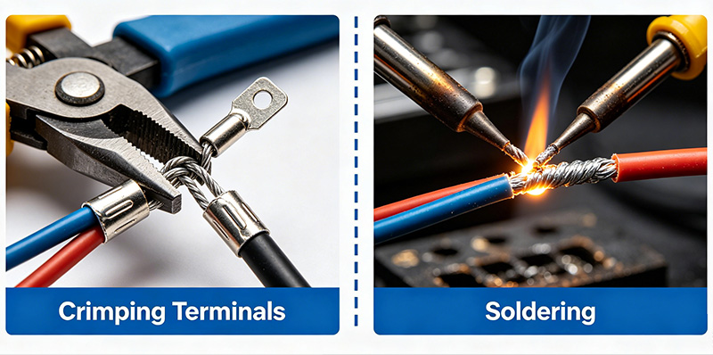
Crimping terminals are electrical connectors designed to create a secure mechanical and electrical connection between a conductor and a terminal by applying pressure with a crimping tool.
During the crimping process, the terminal barrel is compressed around the wire strands, forming a gas-tight connection often referred to as a cold weld.
Common types of crimp terminals include:
● Ring terminals
● Fork terminals
● Pin terminals
● Butt connectors
● Quick disconnect terminals
● Ferrules
● Spade terminals
Crimping terminals are widely used in:
● Industrial control panels
● Power distribution systems
● Automotive wiring harnesses
● Renewable energy systems
● Telecommunications equipment
● Railway electrical systems
● Aerospace applications
A properly executed crimp connection can provide excellent electrical conductivity and long-term reliability without requiring heat.
What Is Soldering?
Soldering is a process that joins wires or components by melting a filler metal (solder) into the joint.
The solder flows between the conductors and solidifies as it cools, creating both mechanical and electrical bonding.
Typical soldering applications include:
● Printed circuit boards (PCBs)
● Electronic assemblies
● Prototype development
● Small signal circuits
● Consumer electronics repair
While soldering remains essential in electronics manufacturing, it is increasingly less common for industrial wire termination applications where vibration resistance and field installation efficiency are critical.
Crimping Terminals vs Soldering: Key Differences
Installation Process
Crimping
Crimping requires:
● Wire stripping
● Terminal selection
● Crimping tool application
The entire process can be completed within seconds.
Benefits include:
● Fast installation
● Consistent quality
● No heat required
● Minimal operator skill
Soldering
Soldering requires:
● Surface preparation
● Flux application
● Heating
● Solder application
● Cooling time
The process takes longer and requires greater skill to achieve consistent results.
Winner: Crimping
For production environments and field installations, crimping is significantly faster and more efficient.
Mechanical Strength
Mechanical strength is critical in environments exposed to movement, vibration, or shock.
Crimped Connections
A properly crimped terminal compresses wire strands together to create a highly durable mechanical bond.
Advantages include:
● Excellent pull-out resistance
● High vibration tolerance
● Reduced fatigue failure
● Long service life
Soldered Connections
Although soldered joints can initially be strong, solder often wicks into wire strands.
This creates a rigid section that becomes vulnerable to:
● Bending stress
● Vibration damage
● Wire fatigue
Over time, repeated movement may cause conductor breakage near the solder joint.
Winner: Crimping
Crimped terminals generally provide superior mechanical performance in industrial environments.
Electrical Conductivity Comparison
One common misconception is that soldering always provides better conductivity.
In reality, a properly executed crimp connection can perform just as well—or even better.
Crimped Connections
Professional crimping creates:
● Gas-tight contact
● Low contact resistance
● Stable conductivity
● Excellent current-carrying capability
The compressed metal surfaces eliminate air gaps and reduce oxidation.
Soldered Connections
Solder joints also provide good conductivity, but conductivity depends heavily on:
● Solder quality
● Joint preparation
● Heat control
● Operator skill
Poor soldering can create:
● Cold joints
● Voids
● Increased resistance
Winner: Tie
When correctly executed, both methods provide excellent electrical performance.
However, crimping tends to produce more consistent results in large-scale manufacturing.
Crimped terminals maintain flexibility in the wire strands while providing secure retention.
Advantages include:
● Superior vibration resistance
● Lower risk of conductor fatigue
● Reduced maintenance requirements
Soldering Performance
Soldered joints create rigid sections within the conductor.
Repeated vibration may eventually lead to:
● Cracked solder joints
● Wire breakage
● Connection failure
Winner: Crimping
This is one of the primary reasons automotive and aerospace industries heavily favor crimped terminals.
A correctly crimped terminal creates a gas-tight seal that helps prevent:
● Moisture intrusion
● Oxidation
● Corrosion
When combined with heat-shrink tubing, protection becomes even more effective.
Soldered Connections
Improper soldering can leave gaps where moisture accumulates.
Over time, corrosion may develop, particularly in outdoor environments.
Winner: Crimping
Especially for harsh industrial applications.
Cost Comparison
Crimping Costs
Initial investments include:
● Crimping tools
● Applicators
● Crimp dies
However, operating costs remain low due to:
● Fast processing
● Minimal training
● High productivity
For high-volume production, crimping offers lower overall costs.
Why Most Manufacturers Prefer Crimping Terminals
Today, many industries have standardized on crimping technology.
Key reasons include:
Higher Production Efficiency
Manufacturers can process thousands of wire terminations per day with automated crimping equipment.
Consistent Quality
Automated crimping machines deliver repeatable results with minimal variation.
Improved Reliability
Crimped connections perform exceptionally well under:
● Vibration
● Temperature changes
● Mechanical stress
Lower Maintenance
Reliable connections reduce downtime and maintenance expenses.
Industry Compliance
Many international standards favor crimped wire terminations for critical applications.
Applications Where Crimping Terminals Are Preferred
Automotive Industry
Modern vehicles contain hundreds of electrical connections.
Crimp terminals are preferred because they:
● Resist vibration
● Support mass production
● Improve long-term reliability
Industrial Automation
Control cabinets and PLC systems require dependable wire terminations.
Crimping terminals help maintain stable electrical performance.
Renewable Energy Systems
Solar farms and wind turbines rely on crimped connections due to their durability and weather resistance.
Telecommunications
Communication systems require low-resistance connections capable of operating for years without failure.
Aerospace and Railways
Safety-critical systems depend on crimp technology because of its proven reliability under extreme operating conditions.
When Soldering May Be the Better Choice
Although crimping dominates industrial wiring applications, soldering remains valuable in specific situations.
Examples include:
PCB Assembly
Electronic circuit boards require soldering for component mounting.
Fine Electronic Work
Small conductors and delicate components may be easier to solder.
Prototyping
Engineers often use soldering during development and testing stages.
Low-Vibration Environments
Fixed electronic equipment may not require the mechanical advantages of crimping.
In these cases, soldering remains an effective solution.
How to Achieve Reliable Crimp Connections
Even the best crimp terminal can fail if installed incorrectly.
Follow these best practices:
Choose the Correct Terminal
Select terminals based on:
● Wire gauge
● Current rating
● Voltage rating
● Environmental conditions
Use Professional Crimping Tools
Avoid generic pliers or improper tools.
Use manufacturer-approved crimping equipment.
Verify compliance with:
● UL
● CE
● RoHS
● ISO 9001
Product Range
A reliable manufacturer should offer:
● Ring terminals
● Fork terminals
● Pin terminals
● Ferrules
● Butt connectors
Customization Capability
Industrial projects often require customized terminal solutions.
Technical Support
Experienced suppliers can recommend the best terminal design for your application.
Conclusion
So, is crimping terminals better than soldering?
For most industrial, automotive, telecommunications, renewable energy, and power distribution applications, the answer is yes.
Crimped connections offer superior vibration resistance, faster installation, greater consistency, lower production costs, and excellent long-term reliability. These advantages explain why modern manufacturers increasingly rely on crimping terminals instead of soldered wire connections.
Soldering still plays an important role in PCB assembly and electronics manufacturing, but when it comes to wire termination in demanding environments, crimping remains the industry standard.
By selecting high-quality crimp terminals and using proper installation techniques, businesses can achieve safer, stronger, and more reliable electrical connections for years to come.
Looking for High-Quality Crimping Terminals?
As a professional Crimp Terminal Manufacturer, we provide reliable crimping terminals, wire connectors, ferrules, and customized electrical connection solutions for industrial, automotive, and power distribution applications. Contact us today to find the right terminal products for your project.
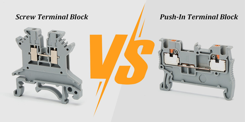
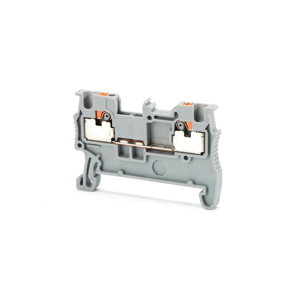
A Push In Terminal Block is a type of electrical connector that allows solid or ferruled stranded wires to be inserted directly into the terminal without tools.
The internal spring mechanism automatically clamps the conductor, creating a secure and vibration-resistant connection.
Key Features of Push In Terminal Blocks
● Tool-free wiring installation
● Spring-force connection technology
● Compatible with DIN rail systems
● High vibration resistance
● Fast wiring speed
● Maintenance-free operation
Push-in technology is widely used in automation systems, PLC control panels, machinery wiring, and industrial electrical distribution systems.
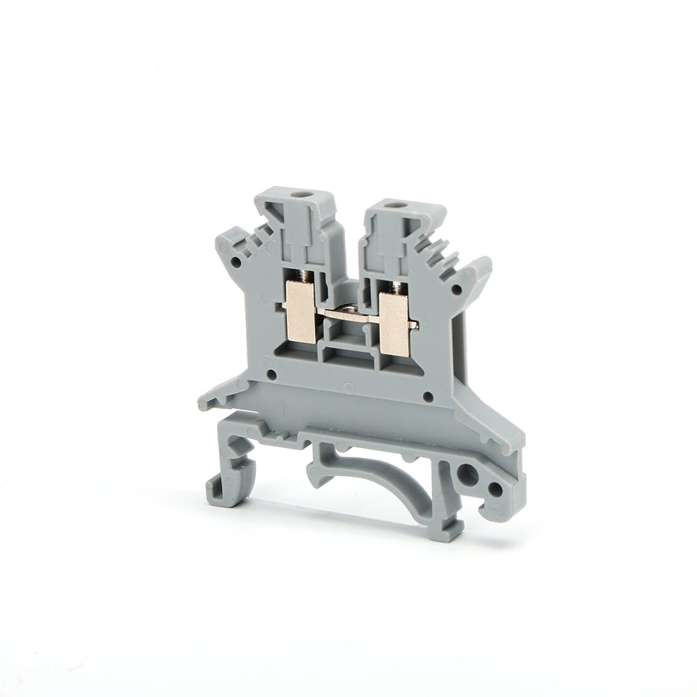
What Is a Screw Terminal Block?
A screw terminal block uses a mechanical screw to clamp and secure the wire conductor.
The wire is inserted into the terminal, and a screwdriver is used to tighten the screw, creating pressure between the metal contact and the conductor.
Key Features of Screw Terminal Blocks
● Traditional and widely used design
● High mechanical clamping force
● Compatible with many wire types
● Low cost and easy availability
● Suitable for heavy-duty applications
Screw terminals have been the industry standard for decades in electrical installations.
Screw VS Push-In Terminal Block: Key Differences
Understanding the differences is essential for selecting the right solution for industrial wiring systems.
1. Wiring Method
Screw Terminal Block
Requires:
● Insert wire
● Tighten screw using tool
Push In Terminal Block
Requires:
● Strip wire
● Insert directly
👉 Push-in systems eliminate tools and reduce installation steps.
2. Installation Speed
● Screw terminal: slower, depends on torque tightening
● Push-in terminal: up to 50% faster wiring time
In large control panels with hundreds of connections, push-in systems significantly reduce labor time.
3. Connection Reliability
Screw Type
● Risk of loosening due to vibration
● Requires periodic maintenance
● Torque-dependent consistency
Push-In Type
● Constant spring force
● Vibration-resistant
● Stable long-term connection
👉 Push-in terminal blocks perform better in high-vibration environments like industrial machines and transportation systems.
4. Maintenance Requirements
● Screw terminal blocks: require re-tightening checks
● Push-in terminal blocks: maintenance-free design
This makes push-in systems more suitable for modern automation industries where downtime must be minimized.
5. Space Efficiency
Push-in terminal blocks are generally:
● More compact
● Designed for high-density wiring
● Easier for modular panel design
Screw terminals require more space due to screwdriver access requirements.
6. Wiring Safety
Screw Terminal Risks:
● Over-tightening damages wire
● Under-tightening causes heat buildup
● Human error in torque control
👉 While screw terminals are cheaper initially, push-in systems reduce total lifecycle cost.
Advantages of Push-In Terminal Blocks
Push-in technology is becoming the preferred solution in modern electrical engineering.
1. Faster Industrial Wiring
Push-in terminals reduce wiring time significantly, especially in mass production control panels.
2. Tool-Free Installation
No screwdriver required → reduces labor complexity.
3. High Vibration Resistance
Spring clamp technology ensures stable contact in harsh environments.
4. Reduced Human Error
No torque dependency → consistent connection quality.
5. Maintenance-Free Operation
Once installed, no periodic tightening is required.
6. Ideal for Automation Systems
Widely used in:
● PLC systems
● Factory automation
● Robotics
● Energy distribution panels
Disadvantages of Push-In Terminal Blocks
Despite advantages, push-in technology has some limitations:
● Slightly higher unit cost
● Requires proper wire stripping length
● Not ideal for all conductor types (depending on design)
● Requires standard-compliant ferrules for stranded wires
Advantages of Screw Terminal Blocks
Screw terminal blocks remain widely used due to their strengths:
1. Universal Compatibility
Works with a wide range of wire types and sizes.
2. Lower Initial Cost
Ideal for budget-sensitive installations.
3. High Clamping Force
Suitable for heavy-duty electrical connections.
4. Easy Replacement
Simple mechanical structure makes maintenance straightforward.
Disadvantages of Screw Terminal Blocks
However, screw-type systems face limitations in modern applications:
● Time-consuming installation
● Risk of loosening under vibration
● Requires periodic maintenance
● Operator-dependent quality
● Higher labor cost in large projects
Screw vs Push-In Terminal Block in Industrial Applications
1. Control Cabinets
Push-in terminals are preferred due to:
● High-density wiring
● Fast assembly
● Reduced maintenance
2. Industrial Automation
Push-in systems dominate because of:
● Vibration resistance
● Reliability
● Modular design compatibility
3. Power Distribution Systems
Screw terminals are still used for:
● Heavy current connections
● Traditional installations
4. Machinery Manufacturing
Push-in technology is increasingly adopted for:
● Faster production cycles
● Reduced assembly errors
Which Is Better: Screw or Push-In Terminal Blocks?
The answer depends on application requirements.
Choose Screw Terminal Blocks if:
● Budget is limited
● Application is low vibration
● Wiring changes are frequent
● Heavy conductor applications are required
Choose Push-In Terminal Blocks if:
● Speed and efficiency are critical
● High reliability is required
● Industrial automation systems are used
● Maintenance reduction is important
👉 In modern industrial design, push-in terminal blocks are increasingly becoming the standard choice.
Future Trend: Why Push-In Terminal Blocks Are Replacing Screw Types
The electrical industry is moving toward:
● Automation
● Modular panel design
● Smart manufacturing
Push-in technology aligns with these trends because it offers:
● Faster installation
● Lower lifecycle cost
● Higher reliability
● Reduced human dependency
Many global electrical manufacturers are gradually shifting their product lines toward push-in systems.
FAQ
1. What is a push in terminal block used for?
It is used for fast, tool-free electrical wire connections in control systems and industrial panels.
2. Are push-in terminal blocks reliable?
Yes, they provide stable spring-force connections with high vibration resistance.
3. What is the main advantage of screw terminal blocks?
Lower cost and compatibility with various wire types.
4. Can push-in terminal blocks handle stranded wire?
Yes, but ferrules are usually recommended for best performance.
5. Why are push-in terminal blocks faster?
Because they eliminate screw tightening and tool usage.
6. Which is safer: screw or push-in terminal blocks?
Push-in terminals generally reduce human error and improve safety consistency.
7. Do push-in terminal blocks need maintenance?
No, they are designed as maintenance-free components.
Conclusion
The comparison between screw vs push-in terminal blocks clearly shows a shift in the electrical industry toward faster, safer, and more efficient wiring systems.
While screw terminal blocks still hold value in traditional and heavy-duty applications, push-in terminal blocks dominate modern industrial automation due to their speed, reliability, and maintenance-free design.
For engineers and system designers, selecting the right terminal block is no longer just about cost—it is about long-term performance, installation efficiency, and system reliability.
Related Product
Warning: Invalid argument supplied for foreach() in /www/wwwroot/westlec.com/wp-content/themes/junj/single.php on line 67



 EN
EN  PT
PT 