

Quick answer: Push-in wire connectors are screwless terminals that grip a prepared conductor with a pre-loaded stainless steel spring. You push the stripped wire straight into the port — no screwdriver, no torque, no twisting — and the spring clamps the conductor against a copper current bar. They are used in junction boxes, control panels, luminaires and DIN rail terminal blocks, and they are covered by IEC 60947-7-1 and UL 1059 for terminal blocks and by UL 486C for inline splicing connectors.
That is the definition. The part that matters to a specifier is what sits behind it: which conductor types the spring can actually hold, what the datasheet ratings mean, and which standard applies to the product you are buying. This article answers all three, with a datasheet decoder and a conductor-compatibility table you can use on the next RFQ.
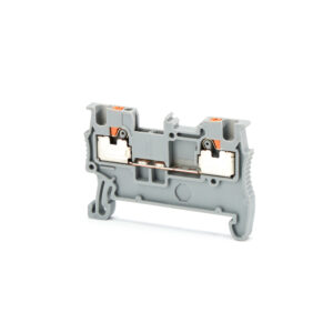 What push-in wire connectors are
A push-in wire connector has three parts: a copper alloy current bar, a pre-tensioned stainless spring, and an insulating housing with one or more entry ports. The spring is held open by the housing geometry. When you insert a stripped conductor, the spring closes onto it and holds it against the current bar with a force that was set in the factory.
Three consequences follow from that design:
- The connection is operator-independent. There is no torque to apply and nothing to re-tighten, so the result does not vary with who did the work.
- The joint stays loaded. A screw terminal relaxes as copper creeps and as the joint cycles thermally. A spring follows the conductor and keeps the force.
- Conductor preparation becomes the variable. Strip length, strand type and whether a ferrule is fitted are what decide whether the spring gets a good grip. This is where most field problems start.
How the spring actually holds the conductor
The spring is not simply pressing on the wire. In a well-designed connector the conductor is clamped between the spring edge and the current bar, and the spring geometry is arranged so that any attempt to pull the wire out increases the clamping force. That is why the failure mode of a good push-in joint is the conductor breaking, not slipping.
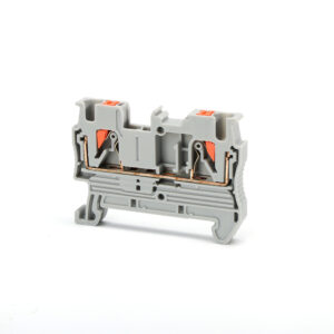 Two detail points for specifiers:
- Contact quality is about the interface, not the force alone. The spring pushes the strands against the tin-plated current bar hard enough to deform them slightly and break through surface oxide, producing a gas-tight contact that does not oxidise further.
- Release is by tool or lever, not by pulling. Releasing requires a screwdriver in the release slot or a lever, depending on the form factor. That is deliberate — it prevents accidental disconnection.
What push-in is not
“Push-in” is often used loosely. This is how it compares with the connection methods it gets confused with:
| Type | How the wire is held | Tool to install | Re-torque needed |
|---|---|---|---|
| Push-in | Pre-loaded spring closes on insertion | None for solid or ferruled wire | No |
| Spring cage | Spring opened with a tool, then clamps | Screwdriver or push button | No |
| Screw | Screw pressure on the conductor | Torque screwdriver | Yes |
| Twist-on wire nut | Tapered spring thread twisted onto the joint | None, but by hand | No |
| Quick-connect | Flat blade slides onto a tab | Crimp tool for the blade terminal | No |
The most common sourcing mistake is buying a push-in product when the application actually needs a spring cage, or the other way round. Our comparison of screw, spring cage and push-in connections sets out where each one belongs.
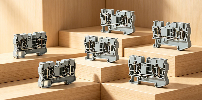
Four form factors you will see on a spec
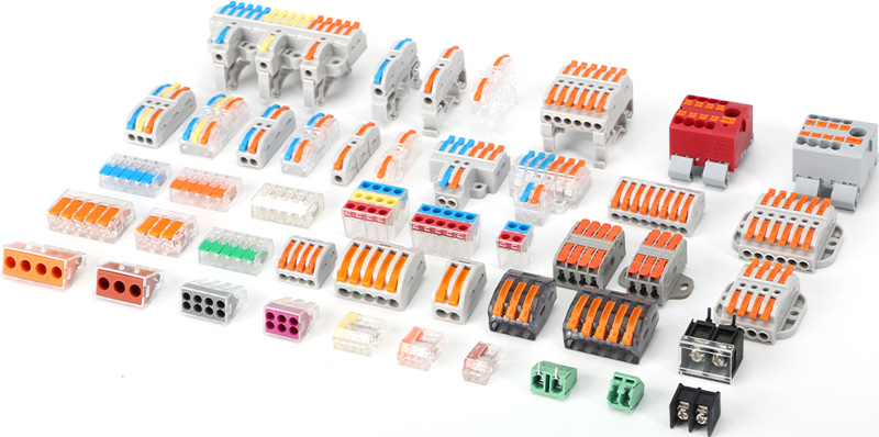
- Inline splicing connectors. The compact multi-port blocks used inside junction boxes and luminaires, typically for 0.5–4 mm² solid or ferruled conductors. In North America these are evaluated to UL 486C for splicing wire connectors.
- Lever connectors. The same principle with a lever that opens the spring, which makes them reusable and lets them accept a wider range of conductor types. Popular for site work and rework.
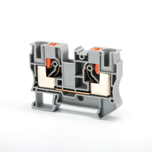
- DIN rail push-in terminal blocks. The industrial form — feed-through, protective earth, multi-level and fuse variants mounted on TS35 rail per IEC 60715. This is the format used in control panels and machinery, and it is the one covered by IEC 60947-7-1 and UL 1059.
- PCB push-in terminals. Soldered to the board, with the push-in clamp on the field-wiring side, common in drivers, controllers and building automation devices.
The form factor you choose changes which standard applies and what the ratings mean, so it is worth being explicit about it on the enquiry. A compact inline connector for a luminaire and a DIN rail terminal block for a motor control centre are both “push-in”, but they are specified, tested and purchased differently.
For panel and machinery work the DIN rail format is the one that matters commercially, and it is where our push-in terminal block range sits — from 1.5 mm² signal sizes through to 16 mm² feed-through and protective earth variants on the same TS35 rail.
 Conductor rules that decide whether the joint holds
This is the single biggest source of field failures, and it is entirely avoidable. A push-in spring is designed around a specific conductor geometry; feed it something different and the grip is compromised even though the wire “goes in”.
| Conductor (IEC 60228) | Direct push-in | What the datasheet must say |
|---|---|---|
| Class 1 – solid | Yes, this is the ideal case | Rated range in mm² and AWG |
| Class 2 – stranded | Often yes, if the strands do not splay | Explicit statement either way |
| Class 5 – flexible | Usually requires a ferrule | Ferrule yes/no, and the ferrule length |
| Class 6 – highly flexible | Only with a ferrule, if approved at all | Written approval for the exact cable type |
Two rules follow from that table. Always respect the stated strip length — too short and the spring clamps insulation, too long and bare copper sits outside the housing. And never push a fine-stranded conductor into a port rated for solid wire; the strands splay, the spring catches only a few of them, and you get a high-resistance joint that looks fine. Our article on preventing strand damage in push-in terminals goes deeper on the mechanism.
Not sure which push-in product fits your conductor?
Send us your cable type, cross-section and panel layout. Our engineering team will confirm the conductor class, the ferrule requirement and the right push-in terminal block — and ship production-lot samples you can terminate and pull-test on your own bench.
Datasheet decoder for push-in connectors
Eight fields carry almost all of the specification risk. If a supplier’s datasheet is missing any of them, ask before you buy.
| Field | What it really tells you | Watch for |
|---|---|---|
| Rated connecting capacity | The conductor range, listed per class | A single range that hides solid vs flexible |
| Rated current and voltage | Thermal and dielectric capability | IEC and UL values that are not both shown |
| Strip length | The preparation the design assumes | A value with no tolerance |
| Ferrule requirement | Whether flexible cable is usable | Silence — assume not approved |
| Rated impulse withstand / pollution degree | Insulation coordination per IEC 60664-1 | Missing overvoltage category |
| Ambient temperature range | Where the rating still applies | No derating curve for hot enclosures |
| Housing material and flammability | PA66 and a UL 94 class, usually V-0 | “Nylon” with no class stated |
| Applicable standard and file number | Which test programme backs the ratings | A logo with no certification reference |
Standards behind the ratings
- IEC 60947-7-1 — terminal blocks for copper conductors, including screwless (push-in and spring cage) clamping units. IEC 60947-7-2 adds the requirements for protective earth terminal blocks and -7-3 for fuse terminal blocks.
- UL 1059 and CSA C22.2 No. 158 — the North American requirements for terminal blocks.
- UL 486C — splicing wire connectors, which is what the compact inline push-in connectors used in junction boxes are evaluated to.
- IEC 60998 series — connecting devices for low-voltage circuits in household and similar fixed installations, where the screwless clamping unit requirements sit.
- IEC 60664-1 for insulation coordination and IEC 60715 for the TS35/7.5 and TS35/15 mounting rail.
- RoHS and REACH for substance compliance, and ISO 9001 for the manufacturing system.
The key point for buyers: IEC and UL ratings are measured under different test programmes and are not interchangeable. A push-in terminal block can legitimately carry different current values in each column, and you must use the value for the market the equipment ships to.
Where push-in works — and where it does not
Strong fits: high-volume panel building where wiring time dominates; solid or ferruled conductors in a controlled harness; junction boxes and luminaires; building automation; any application where re-torquing is impractical or where vibration would loosen a screw.
On the commercial side, the argument is usually about labour rather than components. A push-in termination is a single straight push instead of a screwdriver operation, and across a panel with hundreds of points the time saved is substantial. The saving is largest where the conductor is consistent and prepared in advance — which is exactly the case in series panel building. Where cable types vary from point to point, the advantage narrows, because each termination has to be checked against the conductor class before it is made.
Poor fits: fine-stranded cable without ferrules; very large conductors, where a bolted or compression connection is more practical; joints that will be re-made frequently, where a lever or screw terminal is more forgiving; and aluminium conductors, which need a specifically approved design and surface treatment rather than a copper-rated clamp.
Selection checklist for buyers
- Confirm the conductor class you actually buy — do not specify from the cross-section alone.
- Check the rated connecting capacity for that class, in both mm² and AWG.
- Decide the ferrule policy and write it into the work instruction.
- Read both the IEC and the UL/CSA column and use the one that applies to your market.
- Confirm the housing flammability class and the ambient temperature range with derating.
- Check rail and accessory compatibility — jumpers, markers, end covers and PE variants should come from the same family.
- Ask for pull-out and temperature-rise test evidence, plus lot traceability and a change-control policy.
Two examples from our own range: the VPT 2.5 push-in terminal block for general 2.5 mm² control wiring, and the VPT 4 push-in terminal block where a larger conductor or a higher current is needed — both share jumpers, markers and end covers with the rest of the family.
On long-term reliability, the question comes up in almost every evaluation; we answer it directly in are push-in wire connectors reliable.
Specifying push-in terminal blocks this quarter?
Send us your conductor sizes, volumes and target market. WESTLEC returns IEC and UL datasheets, test evidence and production-lot samples — usually within three working days.
Frequently asked questions
1. What are push-in wire connectors used for?
They are used anywhere a joint has to be made quickly and repeatably: junction boxes and luminaires, DIN rail control panels, building automation devices, driver and controller PCBs, and machinery harnesses. They are chosen where wiring time matters and where re-torquing a screw would be impractical.
2. How does a push-in connector hold the wire?
A pre-tensioned stainless steel spring is held open by the housing. Inserting the stripped conductor releases it, and the spring clamps the conductor against a tin-plated copper current bar, deforming the strands enough to break through surface oxide and form a gas-tight contact. The geometry means pulling the wire increases the grip rather than releasing it.
3. Can you use stranded wire in a push-in connector?
Sometimes. Standard Class 2 stranded conductors are accepted by many designs, but fine-stranded Class 5 and Class 6 cable generally requires a bootlace ferrule. The datasheet must state which conductor classes are approved — if it does not say, assume stranded is not covered.
4. Do push-in connectors need ferrules?
Solid conductors do not. Fine-stranded flexible conductors usually do, because loose strands splay when they meet the spring and only a few are captured. Where a ferrule is required, use the stated ferrule length and crimp profile so the ferrule seats fully in the port.
5. Are push-in wire connectors reusable?
Technically yes — the wire is released with a screwdriver in the release slot or by operating the lever, depending on the type. In production practice, check the manufacturer’s stated re-termination cycles; springs are designed for a finite number of operations, and a re-made joint should always be re-checked.
6. How is push-in different from spring cage?
Both use a spring and neither needs re-torquing. The difference is actuation: a push-in accepts a prepared conductor with no tool, while a spring cage is opened with a screwdriver or button first. Spring cage usually tolerates a wider range of conductor types without a ferrule; push-in is generally faster on consistent, prepared wire.
7. Are push-in connectors as reliable as screw terminals?
In vibration and thermal-cycling duty, generally yes or better, because the spring maintains force as the conductor settles and there is no torque to relax. The condition is conductor preparation: a push-in joint made with the wrong conductor class or the wrong strip length is less forgiving than a correctly torqued screw terminal.
8. What standards apply to push-in wire connectors?
IEC 60947-7-1 covers screwless clamping units in terminal blocks, with UL 1059 and CSA C22.2 No. 158 for North America. Compact inline splicing connectors are evaluated to UL 486C, and the IEC 60998 series covers connecting devices for household and similar fixed installations. Insulation coordination is assessed per IEC 60664-1 and rail mounting per IEC 60715.
Conclusion
Push-in wire connectors are a spring-clamped, tool-free alternative to screw terminals that remove installer torque from the quality equation. Their reliability is high when the conductor class, strip length and ferrule policy are respected, and their economics are strongest where wiring time dominates.
For a buyer, the work is not in understanding the concept — it is in reading the datasheet properly. Confirm the rated connecting capacity by conductor class, read both the IEC and the UL column, and ask for pull-out and temperature-rise evidence. Those three checks separate a push-in terminal block you can standardise on from one you will re-qualify later.
About the author
This article was written by the WESTLEC engineering team. WESTLEC manufactures low-voltage electrical connection products — rail-mounted terminal blocks in screw, spring cage and push-in connection, crimp terminals, copper tube terminals, busbars and waterproof cable glands — at our factory in Yueqing, Zhejiang, China, under an ISO 9001 quality management system. Our products are supplied to panel builders, machine builders and distributors in Europe, North America, the Middle East and Southeast Asia.
Last reviewed: September 2026. Standards referenced: IEC 60947-7-1, IEC 60947-7-2, IEC 60947-7-3, IEC 60664-1, IEC 60715, IEC 60998, IEC 60228, UL 1059, CSA C22.2 No. 158, UL 486C, UL 94, RoHS, REACH.
 EN
EN  PT
PT