


Quick answer: Electrical resistance testing — usually a four-wire (Kelvin) millivolt-drop test — is the only non-destructive way to measure whether a fork crimp terminal actually makes a good electrical joint. You pass a known DC current through the crimped assembly, measure the voltage drop across the crimp, and divide to get resistance. A sound crimp measures no more than the resistance of an equivalent length of the conductor itself, which for a small fork terminal is a fraction of a milliohm. This article gives the reference values, the test procedure, the error sources and the pass/fail bands.
A fork crimp terminal can look perfect and still be electrically marginal. The strands may not have filled the barrel, the crimp may be a fraction of a millimetre too high, or the plating may have been scored during forming — none of which is visible once the sleeve is on. Resistance testing is what turns “it looks fine” into a number you can put in a quality record.
What resistance testing tells you about a fork crimp
A crimped connection is a mechanical joint. Its electrical quality comes from the contact area between the compressed copper strands and the inside of the barrel, and from the absence of oxide or voids in that interface. Resistance is the direct electrical expression of that interface.
Three things make the test worth running:
- Heat is the failure mode you are preventing. A high-resistance crimp dissipates power (P = I²R) every time the circuit is loaded. That heat softens insulation, anneals the copper, oxidises the interface further and raises the resistance again — a slow thermal runaway that ends in a burnt terminal.
- It is non-destructive. Unlike a pull test, the sample survives, so you can test first-off pieces and still use them.
- It is fast and repeatable. A trained operator runs a sample in under a minute, which makes it practical for in-process checks as well as for incoming inspection.
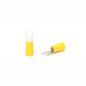
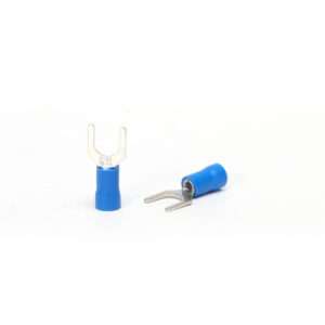
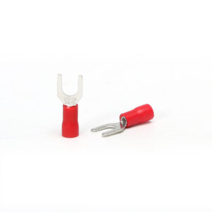
Our range of vinyl insulated fork terminals is dimensioned so that a correctly set tool produces a crimp in the band described below — but the measurement is what proves it.
Why two probes are not enough
A good small fork crimp measures in the order of 0.05–0.15 mΩ. The resistance of a pair of test leads, the probe contact points and the clip-to-terminal interface is typically tens of milliohms. On a two-wire meter you would be reading your own test leads, not the crimp.
The fix is the four-wire (Kelvin) method:
- Two current leads pass the test current through the assembly.
- Two voltage sense leads touch points inside the current connections and measure the drop. Because the meter input draws almost no current, no voltage is dropped across the sense lead and contact resistance, so it cancels out.
Any instrument described as a micro-ohmmeter, a milliohmmeter with Kelvin terminals, or a benchtop DMM in four-wire resistance mode will do this. What matters more than the meter is where you put the probes — see the procedure below.
 Reference values by conductor size
The classic acceptance criterion is that the resistance of a crimped connection should not exceed the resistance of an equal length of the conductor it joins. The table below gives that reference, calculated from the resistivity of copper (ρ = 1.7241 × 10⁻⁸ Ω·m at 20 °C) for a 10 mm length — roughly the length of a small fork terminal barrel.
| Conductor | AWG | R of 10 mm copper at 20 °C | mV drop at 1 A | mV drop at 10 A |
|---|---|---|---|---|
| 0.34 mm² | 22 | 0.529 mΩ | 0.53 mV | 5.29 mV |
| 0.50 mm² | 20 | 0.333 mΩ | 0.33 mV | 3.33 mV |
| 0.82 mm² | 18 | 0.209 mΩ | 0.21 mV | 2.09 mV |
| 1.31 mm² | 16 | 0.132 mΩ | 0.13 mV | 1.32 mV |
| 2.08 mm² | 14 | 0.083 mΩ | 0.08 mV | 0.83 mV |
| 3.31 mm² | 12 | 0.052 mΩ | 0.05 mV | 0.52 mV |
| 5.26 mm² | 10 | 0.033 mΩ | 0.03 mV | 0.33 mV |
Read those numbers again: the values you are measuring are microvolts to a few millivolts. That is why the method matters more than the meter, and why a 2 mΩ reading on a 1.5 mm² crimp is not a rounding error — it is roughly fifteen times the resistance of an equal length of conductor.
For the metric fork sizes commonly used in control panels, the same calculation gives: 1.25 mm² → 0.138 mΩ, 2.0 mm² → 0.086 mΩ, 3.5 mm² → 0.049 mΩ, 5.5 mm² → 0.031 mΩ per 10 mm.
 Step-by-step test procedure
- Condition and record temperature. Test at 20 °C ± 5 °C where possible. If not, record the temperature and correct the reading: R20 = Rt ÷ [1 + 0.00393 (t − 20)], where 0.00393 is the temperature coefficient of copper.
- Select the test current. High enough to give a readable drop, low enough not to heat the joint. A practical range for small fork terminals is 1–10 A DC; where your specification states a current, use that.
- Make the current connections outside the sense points. Clamp the current leads to the conductor well back from the barrel and to the terminal tongue or pad. Current must flow through the whole joint.
- Place the sense probes at the barrel mouths. Put one on the conductor immediately where it enters the barrel and one on the fork tongue immediately where it leaves. This captures the barrel-to-conductor interface — which is the crimp — and not the bulk conductor.
- Cancel offset and thermal EMF. Zero the instrument with the leads shorted, or take readings with the current in both directions and average the two magnitudes. Dissimilar-metal junctions generate a small voltage of their own that can exceed your signal.
- Energise, settle, read. Wait a few seconds for thermal and electrical settling, record the millivolt drop, and calculate R = V ÷ I.
- Compare and record. Compare against your limit, and log crimp height, tool identity, operator and operator shift alongside the resistance value. Resistance without crimp-height context is half a record.
As a worked example: a 2 mm² fork terminal tested at 10 A gives a drop of 0.94 mV. R = 0.94 mV ÷ 10 A = 0.094 mΩ. The reference for 2 mm² is 0.086 mΩ, so the ratio is 1.09 — acceptable, but close enough to justify checking the crimp height and the strand fill before releasing the batch.
Interpreting the reading
| Measured R ÷ reference R | Verdict | Typical cause | Action |
|---|---|---|---|
| ≤ 1.0 | Good | Full strand fill, gas-tight interface | Release; log the value |
| 1.0 – 2.0 | Acceptable, watch | Slightly high crimp height or short strip length | Check crimp height and probe placement, retest |
| 2.0 – 5.0 | Marginal | Under-crimp, missing strands, damaged plating | Hold the batch; verify tool setting and conductor size |
| > 5.0 | Fail | Wrong die, wrong terminal size, oxide or contamination | Quarantine, rework or scrap, re-qualify the tool |
These bands are a practical starting point for in-house process control. The binding limit is the one written in your product specification, customer standard or applicable national standard — always defer to that when it exists.
Want reference values for your exact terminal sizes?
Tell us the fork terminal sizes and conductors you build with. Our engineering team will return measured resistance and pull-out data for production samples, with the test current and probe positions documented so your team can reproduce the result.
Five errors that produce false readings
- Measuring with two wires. You will read your leads. Values above a few milliohms on a small terminal almost always mean a two-wire setup.
- Test current too low for the meter. At 1 A a 1.5 mm² crimp produces about 0.13 mV. If your instrument cannot resolve tens of microvolts, raise the current rather than guessing.
- Ignoring thermoelectric EMF. Copper-to-tin and copper-to-nickel junctions generate their own voltage. Reverse the current and average, or use an instrument with offset compensation.
- Heating the sample. A large current left on too long raises the joint temperature and the reading. Energise briefly and let samples cool between tests.
- Measuring the wrong span. If your sense probes sit on the conductor either side of the barrel rather than across it, you are measuring wire, not crimp. Define the span in your work instruction and keep it identical between samples.
Where resistance testing fits among the other crimp checks
Resistance testing is powerful but not sufficient on its own. A complete crimp qualification stacks four methods:
- Visual and dimensional. Crimp height measured with a micrometer and go/no-go gauge, typically held to about ±0.05 mm on small terminals and ±0.10 mm on power sizes. Catches tool drift before it becomes a resistance problem.
- Resistance (this article). Non-destructive, fast, measures the actual electrical result.
- Pull-out / secureness. Covered by IEC 60352-2 and UL 486A-486B. The acceptance criterion that matters is the failure mode — the conductor should break before it pulls out of the barrel.
- Cross-section analysis. Destructive metallographic section used to qualify a new tool, die or terminal design, and to calibrate the other three.
Used together, these four give you a closed loop: dimensional drift shows up as rising resistance, and rising resistance shows up as reduced pull force. It also helps to know which variables were fixed before the terminal reached your bench — barrel material, annealing and plating thickness all set the floor on how low your reading can go. Our article on how high quality fork terminals are manufactured covers that upstream side.
Installing the terminal correctly is the other half of the equation — our guide to installing fork crimp terminals correctly covers the assembly side.
Standards behind the method
When you write a test instruction, cite the standard your customer recognises:
- IEC 60352-2 — solderless crimped connections; covers electrical (voltage drop / resistance) measurement along with mechanical and conditioning tests
- UL 486A-486B — wire connectors for copper conductors; covers secureness, pull-out and temperature-rise performance
- USCAR-21 — automotive cable-to-terminal crimp performance, including a millivolt-drop test, widely applied in harness production
- EN/IEC 61238-1 — compression connectors for power cables, where resistance is measured across heat-cycling sequences
- IPC/WHMA-A-620 — cable and wire harness workmanship acceptance criteria
- ISO 9001, and IATF 16949 where the harness is automotive
Note that standards usually specify the conditioning sequence and the limit, not your shop-floor sampling plan. The sampling plan is yours to define — see below.
Sampling and records that make the test worth running
| Trigger | Sample | Record |
|---|---|---|
| New tool, die or terminal size | 5 pieces, plus cross-section on 1 | Crimp height, resistance, pull force, section photo |
| Start of shift or batch | 3 pieces | Crimp height and resistance, tool ID, operator |
| After a tool adjustment or conductor change | 3 pieces | Full re-qualification of first-off |
| Incoming inspection of a new lot | 3 pieces per size | Resistance, plating appearance, dimensional check |
Keep the results on a simple control chart. A slow upward drift in resistance is usually the first sign that a die is wearing or that a crimp-height setting has moved — and it appears long before any sample actually fails.
Our SV 2 fork terminal and SV 5.5 fork terminal are supplied with dimensional data that lets you set crimp height and verify resistance on the same samples.
Qualifying fork crimp terminals for a new harness?
Send us your conductor sizes, crimp tooling and target standard. WESTLEC supplies production-lot samples with dimensional, resistance and pull-out data so your quality team can approve the part without a second test round.
Frequently asked questions
1. What is electrical resistance testing?
It is a measurement of the resistance of the crimped joint, usually performed as a four-wire millivolt-drop test: a known DC current is passed through the assembly and the voltage drop across the crimp is measured and divided by the current. The result tells you whether the crimp formed a gas-tight, low-resistance interface.
2. What resistance should a good fork crimp have?
As a rule of thumb, no more than the resistance of an equal length of the conductor. For a 1.5 mm² crimp that is around 0.13 mΩ for a 10 mm length; for 2.5 mm² about 0.07 mΩ. Where your specification or standard states a limit, that number governs.
3. Do I really need a four-wire meter?
Yes for small terminals. Lead and contact resistance is tens of milliohms, while the crimp is a fraction of a milliohm, so a two-wire reading tells you almost nothing about the joint. A milliohmmeter with Kelvin terminals or a benchtop DMM in four-wire mode is the practical minimum.
4. What test current should I use?
High enough for a readable drop and low enough not to heat the joint — 1–10 A DC is a common practical range for small fork terminals. If your specification, or the applicable standard such as USCAR-21, states a current, use that value so your results are comparable with the supplier’s.
5. Can I test a fork terminal after it is installed?
Yes, provided you can access both the conductor side and the tongue side with four probes and the circuit is de-energised and isolated. Measure across the crimp span only; the resistance of the mating stud, screw or tab interface is a separate joint and will dominate the reading if you include it.
6. Why does my reading change with temperature?
Copper has a temperature coefficient of about 0.00393 per °C, so resistance rises with temperature. Test near 20 °C where possible, or correct the reading using R20 = Rt ÷ [1 + 0.00393 (t − 20)] and record the temperature with every measurement.
7. Is a low resistance reading enough to approve a crimp?
On its own, no. Resistance is a good screening test but a crimp can measure low and still be mechanically weak if, for example, only part of the strand bundle was captured. Pair it with crimp-height measurement on every sample and with periodic pull-out and cross-section checks.
8. How often should resistance be tested in production?
First-off checks whenever a tool, die, terminal size or conductor lot changes, then a small sample — typically three pieces — at the start of each shift or batch. Plot the values on a control chart; a slow drift is more informative than any single pass or fail result.
Conclusion
Electrical resistance testing turns crimp quality from an opinion into a number. Run it four-wire, at a defined test current, across the barrel span, with thermal EMF cancelled and the temperature recorded, and compare against the resistance of an equal length of conductor. Values above roughly double that reference are a signal to stop and check the tool before the batch grows.
Used alongside crimp-height measurement, pull-out testing and occasional cross-section analysis, it gives you a crimp process you can actually defend — to a customer auditor, to an automotive quality system, or simply the next time a harness comes back from the field.
About the author
This article was written by the WESTLEC engineering team. WESTLEC manufactures low-voltage electrical connection products — crimp terminals including fork, ring, butt splice, pin and blade types, copper tube terminals, rail-mounted terminal blocks, busbars and waterproof cable glands — at our factory in Yueqing, Zhejiang, China, under an ISO 9001 quality management system. Barrels are drawn from ETP copper (C11000, Cu ≥ 99.9%) and tin plated to ASTM B545 service classes.
Last reviewed: September 2026. Standards referenced: IEC 60352-2, UL 486A-486B, USCAR-21, EN/IEC 61238-1, IPC/WHMA-A-620, ASTM B545.
 EN
EN  PT
PT 